Lecture 2.3 notes on Introduction to Computer Vision by Andreas Geiger
Photometric Imahe formation
- Light is emitted by one or more light sources and reflected or refracted (once or multiple times) at surfaces of objects (or media) in the scene
Rendering Equation
Let \(\textbf{p} \in \mathcal{R}^3\) denote a 3D surface point, \(\textbf{v} \in \mathcal{R}^3\) the viewing direction and \(\mathcal{r} \in \mathcal{R}^3\) the incoming light direction.
The rendering equation describes how much of the light \(L_{in}\) with wavelength \(\lambda\) arriving at p is reflected into the viewing direction v:

- \(\omega\) is the unit hemisphere at normal n = The bidirectional reflectance distribution function BRDF(p, r, v, \(\lambda\)) defines how light is reflected at an opaque surface.
- \(L_{emit} > 0\) only for light emitting surfaces.
Diffuse and Specular Reflection
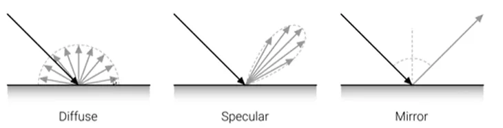
- Typical BRDFs have a diffuse and speculr component
- The diffuse (=constant) component scatters light uniformly in all directions.
- This leads to shading, i.e. smooth variation of intensity wrt. surface normal
-
The specular component depends strongly as the outgoing light direction.
- BRDFs can be very complex and spatially varying
Fresnel Effect
- The amount of light reflected from a surface depends on the viewing angle.
Global Illumination
- Modeling one light is bounce is insufficient for rendering complex scenes.
- Light sources can be shadowed by occluders and rays can bounce multiple times.
- Global illumination techniques also take indirect illumination into account.
Why camera lenses:
- Large and very small pinholes result in image blur (averaging, diffraction).
- Small pinholes require very long shutter times (motion blur)
Optics
- Cameras use one or multiple lenses to accumulate light on the sensor plane.
- Importantly, if a 3D point is in focus, all light rays arrive at the same 2D pixel
- For many applications is suffices to model lens cameras with a pinhole model.
- However to address focus, vignetting and aberration we need to model lenses.
Thin Lens Model
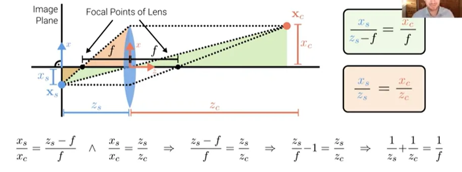

- The thin lens model with spherical lens is often used as an approximation
- Properties: Axis-parallel rays pass the focal point, rays via center keep direction
- From snell’s law we obtain \(f = \frac{R}{2(n - 1)}\) with radius R and index of refraction n
Depth of Field
-
The image is in focus if \(\frac{1}{z_s} + \frac{1}{z_c} = \frac{1}{f}\) where f is the focal length of the lens.
-
For \(z_c -> \inf\) we obtain zs = f (lens with focal length f \(\approx\) pinhole at distance f)
-
If the image plane is out of focus, a 3D point projects to the circle of confusion c.
-
To control the size of the circle of confusion, we change the lens aperture
-
The aperture is a hole or an opening through which light travels
-
The aperture limits the amount of light that can reach the image plane.
-
Smaller apertures lead to sharper, but more noisy images (less photons).
-
The allowable depth variation that limits the circle of confusion c is called depth of field and is a function of both the focus distance and the lens aperture.
-
Typical DSLR lenses have depth of field indicators.
-
The commonly displayed f-number is defined as \(N = \frac{f}{d}\)
-
It is the focal length f divided by the aperture diameter d
-
It is the distance between the nearest and farthest objects that are acceptably sharp.
-
Decreasing the aperture diameter (increasing the f-number) increases the DOF.
Chromatic Aberration
- The index of refraction for glass varies slightly as a function of wavelength.
- Thus, simple lenses suffer from chromatic aberration which is the tendency for light of different colors to focus at slightly different distances (blur, color shift)
- To reduce chromatic, and other kinds of aberrations, most photographic lenses are compound lenses made of different glass elements (with different coatings).
Vignetting
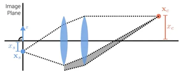
- The tendency for the brightness to fall off towards the image edge.
- Composition of two effects: natural and mechanical vignetting
- Natural vignetting: foreshortening of object surface and lens aperture.
- Mechanical vignetting: The shaded part of the beam never reaches the image.
- Vignetting can be calibrated (i.e. undone)